Process description
Input data preprocessing
Merchant line Mendrisio-Cagno target flow
The Mendrisio-Cagno interconnection line between Switzerland and Italy is a Merchant Line (i.e., operated by private investors) whose power exchange and capacity are handled by specific contracts. For this reason, the Mendrisio PST is used to enforce the active power flow on the interconnection line to a specified target which is provided as an input to the process.
First, the target flow on the interconnection (and the PST) is calculated:
- For D2CC, the Mendrisio-Cagno target flow calculation is based on the following input files:
D2CC inputs contain multiple values that are admissible as target flows for the Mendrisio-Cagno merchant line:
- The value defined in the NTC annual file.
- The values defined in the Target CH file if the associated outage is actually applied on the CGM. The minimum value among all the admissible target flows is selected, with a potential offset (that can be either positive or negative) whose value is the load associated with the Mendrisio node in the CGM.
- For IDCC, the Mendrisio-Cagno target flow is directly retrieved from the NTC annual input.
When the target flow is correctly calculated, it is applied as a regulation value for the Mendrisio PST, and the flow regulation is then activated. This ensures that the loadflow and sensitivity computation engines will automatically change PST taps to maintain the flow on the PST approximately equal to the target flow.
ℹ️ By default, UCTE import in PowSyBl does not set PSTs as regulated, which is why the Mendrisio PST has to be manually set as regulated. Some tests have been conducted in the past to set PST regulation as active by default when regulations are specified in the UCTE network, but this approach caused CSE networks to no longer converge in AC, preventing further progress in this direction. This approach may be reassessed in the future when the resilience of the loadflow engine is improved.
PiSa HVDC alignment
The PiSA HVDC line is an HVDC interconnection between France and Italy composed of two HVDC links.
As the UCT format does not allow modeling such a device in the CGM, an equivalent model is used, consisting of three AC lines and two generators for each HVDC link.
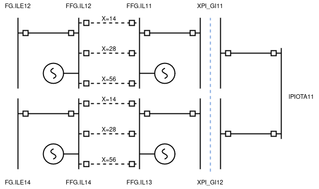
Each HVDC link can be operated in two modes:
- Fixed set point: all AC lines are disconnected, and the generators are configured with a power set point equal to the target flow of the link (each side of the HVDC must have approximately opposite target flows, with signs depending on the direction of flow at the border)
- AC emulation: one AC line is connected (only one should be connected at any time, depending on the angle droop gain coefficient actually used for regulation), and the generators' power set points are equal to 0.
It is possible that, for various reasons, the initial modeling of the PiSa HVDC is not correctly aligned. To address this issue, the equivalent model's generators' power set points are aligned. The generator with the maximum power set point in absolute value is considered as the reference for the HVDC set point: the other generator's power set point is set to the opposite value.
All HVDC aligned set points are saved as they will be used at the end of the process during the TTC res export.
⚠️ For the IDCC process, an extra preprocessing step is applied, forcing the HVDC into fixed set point mode, with a set point value depending on available remedial actions in the CRAC. This process is described in the PiSa setpoint section.
? Open questions:
- In D2CC, the HVDC seems to be implicitly operated in fixed set point mode, but it is never checked whether AC lines are open. Should we open them to ensure there are no issues?
CRAC/CGM alignment
Busbar change
Some topological remedial actions defined in the CRAC file involve moving a branch connection from one node to another. Since the CGM is not detailed enough—lacking all the switches needed to model such an operation—a preprocessing step is performed to ensure that these remedial actions are correctly taken into account during the optimization.
First, if the destination node does not exist in the initial network file, it is created during the preprocessing.
Then, to avoid having to change the network topology, a fictive node is created. This allows the conversion of busbar change remedial actions into sets of switch opening/closing remedial actions.
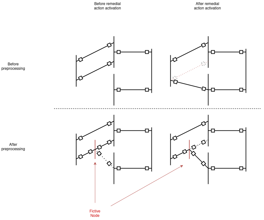
These modifications are saved so that these fictive nodes can be removed before exporting the Final CGM.
? Open questions:
- The Initial CGM output (i.e., output after initial shift) does not seem to be post-processed to remove these fictive nodes created to model the busbar change. Is this normal?
PiSa setpoint
For the IDCC process only, if the HVDC link is operated in AC emulation, the following treatment is applied:
- The HVDC link is switched to fixed set point mode; the equivalent model's generators are connected and the equivalent model's AC lines are disconnected.
- The generators' set points are calculated based on their diagram limits in the CGM and available "HVDC" remedial actions on the equivalent generators in the CRAC file. We consider the intersection of each generator's admissible active power range, both in the CGM and available RAs. The chosen set point is the maximum set point from France to Italy within this intersection.
? Open questions:
- Why is the IDCC treatment different from the D2CC one? Is it justified, or is it only due to the fact that the equivalent model in D2CC input is always in fixed set point mode? In the latter case, should the code be simplified to ensure there is no unnecessary distinction between these two processes?
PSTs range enforcement
CASTOR is not able to optimize a PST if its initial tap is outside the admissible range defined in the CRAC.
To mitigate the risk of suboptimality caused by removing flexibility in the optimization, the network is pre-processed to adjust the initial tap of PSTs that are outside their admissible ranges (and only these ones). These PSTs are set to their minimal admissible tap.
As this is a pre-processing step applied directly to the network file, this modification will not be visible in the final RAO result, but must be considered as a remedial action, even if not modified later during the RAO step. To make this change visible in the computation result, these PST tap changes are saved to be used at the end of the process during the TTC res export.
? Open questions:
- For the sake of simplicity, we have chosen to always set PSTs to the minimal tap of the admissible range, even if the initial tap was above the maximum tap of the range. Since the PST is optimized, this may not impact the final result, but modifying this logic to use the more intuitive approach of setting to the "nearest tap in the range" could improve convergence of the loadflow.
Splitting factors
The Northern Italian Border capacity calculation aims to provide a maximum Northern Italian import transfer capacity. To simulate an import increase on the Northern Italian border, exports from the border countries (France, Switzerland, Austria, and Slovenia) are increased proportionally, with a fixed proportion throughout the process called the splitting factor.
Splitting factors are calculated based on NTC values by country defined in the NTC annual file, and potentially replaced or shifted based on elements from the NTC reduction file. For each country, the splitting factor is calculated as follows:
However, the existence of merchant lines with fixed contractual flows on some borders requires that this definition of splitting factors be adapted to remove the flows on merchant lines from the reference NTC. This gives the following definition for the reduced splitting factors:
? Open questions:
- Why aren't the splitting factors defined in the NTC annual file used?
Modified CGM export to MinIO
The initial UCTE network file that has been imported from the CGM input file is modified by several pre-processing steps. This modified CGM must be used as the network object throughout the entire capacity calculation process.
The modified network is exported in XIIDM format to be shared by GridCapa microservices. It is saved as an artifact of the task on MinIO at the path CSE/IMPORT_EC/<process_type>/<year>/<month>/<day>/<hour>_<minute>/ARTIFACTS/network_pre_processed.xiidm.
Initial shift to previous NTC
The initial shift is an operation performed before the dichotomy process that aims to upgrade the input network from the Vulcanus exchange level to the NTC level.
Initial NTC retrieval
The following notation will be used for the NTC values defined in the different NTC file inputs:
- The NTC value defined for country c in the NTC annual file is denoted as
- The NTC value defined for country c in the NTC red file is denoted as
- The NTC value defined for country c in the NTC2 file is denoted as
For France, Switzerland, Austria, and Slovenia, the initial NTC for the calculation is retrieved as follows:
- For D2CC:
- if is available and of absolute type
- if is available and of relative type
- otherwise
- For IDCC:
- if is available
- if is available and of absolute type
- if is available and of relative type
- otherwise
For Italy, the initial NTC for the calculation is retrieved as follows:
Flows on non-modelled lines retrieval
The following notation will be used for the non-modelled lines flow values defined in the different NTC file inputs:
- The flow value defined for country c in the NTC annual file is denoted as
- The flow value defined for country c in the NTC red file is denoted as
These values correspond to the fixed flow values of special lines with the attribute "modelized" set to false in those input files:
- if is available and of absolute type
- if is available and of relative type
- otherwise
Shift
The initial shift uses each country's GLSK and applies a one-time shift with the following volumes for each country:
If any generator or load in the GLSK is disconnected, it will be automatically connected. The shift is iterative, meaning it will not necessarily respect the initial shifting factors if any of its blocks becomes saturated earlier than others.
GLSK limitation
In case of GLSK limitation, there are two possibilities:
If GLSK limitation is reached on Italy, all other shift values are amended proportionally to the reachable shift on Italy (the aim is to maintain the same shift proportions across all other countries).
If we denote as the maximum available shift on the GLSK, the new shifts for all countries are defined as follows:
- for in [FR, CH, AT, SI]
If GLSK limitation occurs on any other country, a simple warning log is emitted.
The GLSK limitation applies only in IDCC. In D2CC, if the requested shift is larger than the available shift defined in GSK, the remaining shift is performed:
- using LSK if defined,
- using load adjustment over all load nodes of the country as during D2CF merging process if no LSK is defined.
This applies both to the initial shift and the intermediate shifts in the D2CC process.
? Open questions:
- In case of GLSK limitation on another country, it will create a sum of shifts which is not 0, implying that part of this imbalance will be fixed by loadflow compensation.
- The issue was known as described in this page on GLSK limitations: "On the other hand, if the limiting country is any of the following: Switzerland, France, Slovenia, or Austria, tests are currently being conducted by coreso (as of 1st June 2023) to clarify the behavior. However, it is possible that the delta on NIB loads will be automatically balanced using specific LF (Load Flow) parameters. This aspect is still under development and will be updated once the requirements become clearer."
- In case of GLSK limitation in Italy, it seems that orphan network variants aren't cleared in the process. This needs to be analyzed further.
Loadflow / Divergence
In case of loadflow divergence (either before or after shift), the process is considered failed.
Initial CGM Export to MinIO
The initial CGM network file output is the result of the initial shift to reference NTC.
- For D2CC, it is exported in UCTE format to be retrievable through the GridCapa UI as an output. It can also be retrieved as an output of the task on MinIO at the path CSE/IMPORT_EC/D2CC/<year>/<month>/<day>/<hour><minute>/OUTPUTS/<year><month><day><hour><minute>_2D<dayOfWeek>_CO_CSE1.uct.
- For IDCC, it is exported in UCTE format to be retrievable through the GridCapa UI as an output. It can also be retrieved as an output of the task on MinIO at the path CSE/IMPORT_EC/IDCC/<year>/<month>/<day>/<hour><minute>/OUTPUTS/<year><month><day><hour><minute>_<generationHour><dayOfWeek>_Initial_CSE1.uct.
Dichotomy
Initial step (initial Italian import)
Shift
Between two dichotomy steps, a shift is performed to modify the Italian import level following the step update strategy defined below.
GLSK limitation
Similarly to the initial shift, the GLSK limitation applies also during the dichotomy process.
RAO
The RAO computation is run with CASTOR, a search-tree algorithm developed in OpenRAO. For more information, read the documentation.
Objective function
A non-costly RAO is used in the dichotomy. The objective function is SECURE_FLOW, which means that the algorithm stops as soon as it finds a solution where the minimum margin is positive.
For more detailed information, read the related OpenRAO documentation.
Secure
If the RAO finds at least one set of remedial actions in basecase and after each contingency for which all monitored elements are secure, the exchange value is considered as secure.
Unsecure
If the RAO is unable to find a set of remedial actions for which at least one state (basecase or after contingency) is secure, the exchange level is unsecure.
Divergence
In some situations, the loadflow or the sensitivity computation used inside the RAO diverges. This is due to difficult electrical situations, possibly linked to the network model or to big unbalances linked to the flow distribution after shift or the simulation of a contingency.
Inside the algorithm, the cause of the failure of the computation is due to unrealistic voltage values (UNREALISTIC_STATE in the solver status) or to the maximum number of iterations reached in the Newton-Raphson algorithm (MAX_ITERATION_REACHED in solver status) or in the outerloop (UNSTABLE outerloop status).
In case of divergence, the step is considered as unsecure.
In some cases, the sensitivity computation fails only partially (after a given contingency simulation). In this case, even though the RAO finds secure states after basecase and all the other contingencies, it cannot declare the step as secure because it cannot guarantee the existence of a set of remedial actions that will make the network secure after the failing contingency.
For more information on the loadflow module used in GridCapa, see the OpenLoadflow documentation.
Step update strategy
The step update strategy is divided into two phases:
- while only unsecure Italian import values are found, the next exchange value is the latest computed, decreased by 650 MW. While only secure values are found, the Italian import value increases by 650 MW.
- once at least one secure and one unsecure Italian import value is found, a dichotomy is run: if the lowest unsecure Italian import value computed so far is x MW and the highest secure Italian import value is y MW, the next Italian import value analysed is (x+y)/2.
Dichotomy precision
The computation stops when the difference between the highest secure and the lowest unsecure Italian import levels is lower or equal to 100 MW.
Output data postprocessing
CRAC/CGM alignment rollback
When the dichotomy ends successfully, the final network file with activated preventive remedial actions is exported as an output of the process.
To remove fictive nodes added during busbar change remedial actions preprocessing, a post-processing step is applied that removes fictive nodes, switches, and moves associated branches to the correct real nodes.
Shifted CGM export
The shifted CGM network file output is the final network file with activated preventive remedial actions from the last secure step of the dichotomy.
- For D2CC, it is exported in UCTE format to be retrievable through the GridCapa UI as an output. It can also be retrieved as an output of the task on MinIO at the path CSE/IMPORT_EC/D2CC/<year>/<month>/<day>/<hour><minute>/OUTPUTS/<year><month><day><hour><minute>_2D<dayOfWeek>_CO_Final_CSE1.uct.
- For IDCC, it is exported in UCTE format to be retrievable through the GridCapa UI as an output. It can also be retrieved as an output of the task on MinIO at the path CSE/IMPORT_EC/IDCC/<year>/<month>/<day>/<hour><minute>/OUTPUTS/<year><month><day><hour><minute>_<generationHour><dayOfWeek>_CSE1.uct.
TTC Res export
In case of process success
The TTC res output is an XML file that contains the detailed results of the process including:
- Calculated TTC and MNII
- Limiting CNEC
- Remedial actions selected (preventive and curative)
- Flows calculated on CNECs in the different states of the chronology (preventive, after outage, after curative)
- Exchange values on each border
- Actual splitting factors
For D2CC, it is exported to be retrievable through the GridCapa UI as an output. It can also be retrieved as an output of the task on MinIO at the path CSE/IMPORT_EC/D2CC/<year>/<month>/<day>/<hour><minute>/OUTPUTS/TTC_Calculation<year><month><day>_<hour><minute>_2D0_CO_Final_CSE1.xml. For IDCC, it is exported to be retrievable through the GridCapa UI as an output. It can also be retrieved as an output of the task on MinIO at the path CSE/IMPORT_EC/IDCC/<year>/<month>/<day>/<hour><minute>/OUTPUTS/<year><month><day><hour><minute>_XBID2_TTCRes_CSE1.xml.
In case of failure
In case of process failure, a specific TTC res output is generated that includes details about the reason for the failure.
<?xml version="1.0" encoding="UTF-8" standalone="yes"?>
<Timestamp>
    <Time v="2024-12-16T09:30Z"/>
    <Reason>
        <ReasonCode v="A93"/>
        <ReasonText v="IT issues on CE side"/>
    </Reason>
    <Valid v="0"/>
    <CGMfile v="20241216_1030_2D1_CO_CSE1.uct"/>
    <GSKfile v="20241216_1030_2D1_CO_GSK_CSE1.xml"/>
    <CRACfile v="20241216_1030_2D1_CO_CRAC_CSE1.xml"/>
    <BASECASEfile v="20241216_1030_2D1_CO_CSE1.uct"/>
    <Inputfiles>
        <NTCRedfiles>
            <File>
                <Filename v="20241216_2D1_NTC_reductions_CSE1.xml"/>
                <Country v="IT"/>
                <CreationDateTime v="ntcReductionCreationDatetime"/>
                <Backupfile v="A02"/>
            </File>
        </NTCRedfiles>
        <IDCFfiles>
            <File>
                <Filename v="20241216_1030_2D1_UX0.uct"/>
                <Country v="UX"/>
                <CreationDateTime v=""/>
                <Backupfile v="A02"/>
            </File>
        </IDCFfiles>
    </Inputfiles>
</Timestamp>
The Reason element can change depending on the type of failure that occurs:
- If no secure TTC is found (i.e., all exchange values are unsecure), the reason code is "A98" and the reason text is "No secure TTC found"
- In case of any RAO failure, the reason code is "A93" and the reason text is "IT issues on CE side"
- In case of loadflow divergence during initial shift, the reason code is "A42" and the reason text is "Load flow divergence during calculation"
- In case of interruption, the reason code is "B18" and the reason text is empty
? Open questions:
- The TTC_res generation codebase contains another failure case that is never used in the process codebase: INVALID_FILES. Should we investigate it? Remove it?